Tutorials to read first:
Magic Tutorial #1: Getting Started
Magic Tutorial #2: Basic Painting and Selection
Magic Tutorial #3: Advanced Painting (Wiring and Plowing)
Magic Tutorial #4: Cell Hierarchies
Magic Tutorial #5: Multiple Windows
Netlist Commands introduced in this tutorial:
extract, flush, ripup, savenetlist, trace, writeall
Layout Commands introduced in this tutorial:
channel, route
Macros introduced in this tutorial:
(none)
This tutorial describes how to use Magic's automatic routing tools to make interconnections between subcells in a design. In addition to the standard Magic router, which is invoked by the route command and covered in this tutorial, two other routing tools are available. A gate-array router Garouter permits user specified channel definitions, terminals in the interior of cells, and route-throughs across cells. To learn about the gate-array router read this first then "Magic Tutorial #12: Routing Gate Arrays". Finally Magic provides an interactive maze-router that takes graphic hints, the irouter, that permits the user to control the overall path of routes while leaving the tedious details to Magic. The irouter is documented in "Magic Tutorial #10: The Interactive Router".
The standard Magic router provides an obstacle-avoidance capability: if there is mask material in the routing areas, the router can work under, over, or around that material to complete the connections. This means that you can pre-route key signals by hand and have Magic route the less important signals automatically. In addition, you can route power and ground by hand (right now we don't have any power-ground routing tools, so you have to route them by hand).
The router only makes connections between subcells; to make point-to-point connections between pieces of layout within a single cell you should use the wiring command described in "Magic Tutorial #3: Advanced Painting (Wiring and Plowing) " or the maze router described in "Magic Tutorial #10: The Interactive Router". If you only need to make a few connections you are probably better off doing them manually.
The first step in routing is to tell Magic what should be connected to what. This information is contained in a file called a netlist. Sections 2, 3, 4, and 5 describe how to create and modify netlists using Magic's interactive netlist editing tools. Once you've created a netlist, the next step is to invoke the router. Section 6 shows how to do this, and gives a brief summary of what goes on inside the routing tools. Unless your design is very simple and has lots of free space, the routing probably won't succeed the first time. Section 7 describes the feedback provided by the routing tools. Sections 8 and 9 discuss how you can modify your design in light of this feedback to improve its routability. You'll probably need to iterate a few times until the routing is successful.
A netlist is a file that describes a set of desired connections. It contains one or more nets. Each net names a set of terminals that should all be wired together. A terminal is simply a label attached to a piece of mask material within a subcell; it is distinguishable from ordinary labels within a subcell by its presence within a netlist file and by certain characteristics common to terminals, as described below.
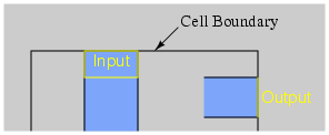
The first step in building a netlist is to label the terminals in your design. Figure 1 shows an example. Each label should be a line or rectangle running along the edge of the cell (point terminals are not allowed). The router will make a connection to the cell somewhere along a terminal's length. If the label isn't at the edge of the cell, Magic will route recklessly across the cell to reach the terminal, taking the shortest path between the terminal and a routing channel. It's almost always a good idea to arrange for terminal labels to be at cell edges. The label must be at least as wide as the minimum width of the routing material; the wider you make the label, the more flexibility you give the router to choose a good point to connect to the terminal.
 |
Terminal labels must be attached to mask material that connects directly to one of Magic's two routing layers (Routing layers are defined in Magic's technology file). For example, in the SCMOS process where the routing layers are metal1 and metal2, diffusion may not be used as a terminal since neither of the routing layers will connect directly to it. On the other hand, a terminal may be attached to diffusion-metal1 contact, since the metal1 routing layer will connect properly to it. Terminals can have arbitrary names, except that they should not contain slashes ("/") or the substring "feedthrough", and should not end in "@", "$", or "^". See Tutorial #2 for a complete description of labeling conventions.
For an example of good and bad terminals, edit the cell tut7a. The cell doesn't make any electrical sense, but contains several good and bad terminals. All the terminals with names like bad1 are incorrect or undesirable for one of the reasons given above, and those with names like good4 are acceptable.
|
If you create two or more terminal labels with the same name in the same cell the router will assume that they are electrically equivalent (connected together within the cell). Because of this, when routing the net it will feel free to connect to whichever one of the terminals is most convenient, and ignore the others. In some cases the router may take advantage of electrically equivalent terminals by using feed throughs: entering a cell at one terminal to make one connection, and exiting through an equivalent terminal on the way to make another connection for the same net.
Magic provides a special menu facility to assist you in placing terminal labels and editing netlists. To make the menu appear, invoke the Magic command
specialopen netlist
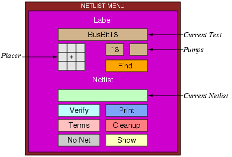
A new window will appear in the lower-left corner of the screen, containing several rectangular areas on a purple background. Each of the rectangular areas is called a button. Clicking mouse buttons inside the menu buttons will invoke various commands to edit labels and netlists. Figure 2 shows a diagram of the netlist menu and Table I summarizes the meaning of button clicks in various menu items. The netlist menu can be grown, shrunk, and moved just like any other window; see "Magic Tutorial #5: Multiple Windows" for details. It also has its own private set of commands. To see what commands you can type in the netlist menu, move the cursor over the menu and type
help
You shouldn't need to type commands in the netlist menu very often, since almost everything you'll need to do can be done using the menu. See Section 9 for a description of a few of the commands you can type; the complete set is described in the manual page magic(1). One of the best uses for the commands is so that you can define macros for them and avoid having to go back and forth to the menu; look up the send command in the man page to see how to do this. The top half of the menu is for placing labels and the bottom half is for editing netlists. This section describes the label facilities, and Section 4 describes the netlist facilities.
The label menu makes it easy for you to enter lots of labels, particularly when there are many labels that are the same except for a number, e.g. bus1, bus2, bus3, etc. There are four sections to the label menu: the current text, the placer, two pumps, and the Find button. To place labels, first click the left mouse button over the current text rectangle. Then type one or more labels on the keyboard, one per line. You can use this mechanism to enter several labels at once. Type return twice to signal the end of the list. At this point, the first of the labels you typed will appear in the current text rectangle.
To place a label, position the box over the area you want to label, then click the left mouse button inside one of the squares of the placer area. A label will be created with the current text. Where you click in the placer determines where the label text will appear relative to the label box: for example, clicking the left-center square causes the text to be centered just to the left of the box. You can place many copies of the same label by moving the box and clicking the placer area again. You can re-orient the text of a label by clicking the right mouse button inside the placer area. For example, if you would like to move a label's text so that it appears centered above the label, place the box over the label and right-click the top-center placer square.
If you entered several labels at once, only the first appears in the current text area. However, you can advance to the next label by right-clicking inside the current text area. In this way you can place a long series of labels entirely with the mouse. Try using this mechanism to add labels to tut7a.
The two small buttons underneath the right side of the current text area are called pumps. To see how these work, enter a label name containing a number into the current text area, for example, bus1. When you do this, the "1" appears in the left pump. Right-clicking the pump causes the number to increment, and left-clicking the pump causes the number to decrement. This makes it easy for you to enter a series of numbered signal names. If a name has two numbers in it, the second number will appear in the second pump, and it can be incremented or decremented too. Try using the pumps to place a series of numbered names.
The last entry in the label portion of the menu is the Find
button. This can be used to locate a label by searching for
a given pattern. If you click the Find button, Magic
will use the current text as a pattern and
search the area underneath the box for a label whose name
contains the pattern. Pattern-matching is done in the same
way as in csh, using the special characters "*",
"?", "
", "[", and "]". Try this on tut7a:
enter "good*" into the current text area, place the box around
the whole cell, then click on the "Find" button. For each of
the good labels, a feedback area will be created with white
stripes to highlight the area. The feedback find command
can be used to step through the areas, and feedback clear
will erase the feedback information from the screen. The feedback
command has many of the same options as drc for getting
information about feedback areas; see the Magic manual page for
details, or type feedback help for a synopsis of the options.
After placing terminal labels, the next step is to specify the connections between them; this is called netlist editing. The bottom half of the netlist menu is used for editing netlists. The first thing you must do is to specify the netlist you want to edit. Do this by clicking in the current netlist box. If you left-click, Magic will prompt you for the netlist name and you can type it at the keyboard. If you right-click, Magic will use the name of the edit cell as the current netlist name. In either case, Magic will read the netlist from disk if it exists and will create a new netlist if there isn't currently a netlist file with the given name. Netlist files are stored on disk with a ".net" extension, which is added by Magic when it reads and writes files. You can change the current netlist by clicking the current netlist button again. Startup Magic on the cell tut7b, open the netlist menu, and set the current netlist to tut7b. Then expand the subcells in tut7b so that you can see their terminals.
|
Netlist editing is done with the netlist tool. If you haven't
already read
"Tutorial #3: Advanced Painting (Wiring and Plowing)",
you should read it now, up through Section 2.1. Tutorial #3
explained how to change the current tool by using the space macro
or by typing tool.
Switch tools to the netlist tool (the
cursor will look like  ).
).
When the netlist tool is in use the left, right, and middle buttons invoke select, toggle, and join operations respectively (see Table II). To see how they work, move the cursor over the terminal right4 in the top subcell of tut7b and click the left mouse button (you may have to zoom in a bit to see the labels; terminals are numbered in clockwise order: right4 is the fourth terminal from the top on the right side). This causes the net containing that terminal to be selected. Three hollow white squares will appear over the layout, marking the terminals that are supposed to be wired together into right4's net. Left-click over the left3 terminal in the same subcell to select its net, then select the right4 net again.
The right button is used to toggle terminals into or out of the current net. If you right-click over a terminal that is in the current net, then it is removed from the current net. If you right-click over a terminal that isn't in the current net, it is added to the current net. A single terminal can only be in one net at a time, so if a terminal is already in a net when you toggle it into another net then Magic will remove it from the old net. Toggle the terminal top4 in the bottom cell out of, then back into, the net containing right4. Now toggle left3 in the bottom cell into this net. Magic warns you because it had to remove left3 from another net in order to add it to right4's net. Type u to undo this change, then left-click on left3 to make sure it got restored to its old net by the undo. All of the netlist-editing operations are undo-able.
The middle button is used to merge two nets together. If you middle-click over a terminal, all the terminals in its net are added to the current net. Play around with the three buttons to edit the netlist tut7b.
Note: the router does not make connections to terminals in the top level cell. It only works with terminals in subcells, or sub-subcells, etc. Because of this, the netlist editor does not permit you to select terminals in the top level cell. If you click over such a terminal Magic prints an error message and refuses to make the selection.
If you left-click over a terminal that is not currently in a net, Magic creates a new net automatically. If you didn't really want to make a new net, you have several choices. Either you can toggle the terminal out of its own net, you can undo the select operation, or you can click the No Net button in the netlist menu (you can do this even while the cursor is in the square shape). The No Net button removes all terminals from the current net and destroys the net. It's a bad idea to leave single-net terminals in the netlist: the router will treat them as errors.
There are two ways to save netlists on disk; these are similar to the ways you can save layout cells. If you type
savenetlist [name]
with the cursor over the netlist menu, the current netlist will be saved on disk in the file name.net. If no name is typed, the name of the current netlist is used. If you type the command
writeall
then Magic will step through all the netlists that have been modified since they were last written, asking you if you'd like them to be written out. If you try to leave Magic without saving all the modified netlists, Magic will warn you and give you a chance to write them out.
If you make changes to a netlist and then decide you don't want them, you can use the flush netlist command to throw away all of the changes and re-read the netlist from its disk file. If you create netlists using a text editor or some other program, you can use flush after you've modified the netlist file in order to make sure that Magic is using the most up-to-date version.
The Print button in the netlist menu will print out on the text screen the names of all the terminals in the current net. Try this for some of the nets in tut7b. The official name of a terminal looks a lot like a Unix file name, consisting of a bunch of fields separated by slashes. Each field except the last is the id of a subcell, and the last field is the name of the terminal. These hierarchical names provide unique names for each terminal, even if the same terminal name is re-used in different cells or if there are multiple copies of the same cell.
The Verify button will check the paint of the edit cell to be sure it implements the connections specified in the current netlist. Feedback areas are created to show nets that are incomplete or nets that are shorted together.
The Terms button will cause Magic to generate a feedback area over each of the terminals in the current netlist, so that you can see which terminals are included in the netlist. If you type the command feedback clear in a layout window then the feedback will be erased.
The Cleanup button is there as a convenience to help you cleanup your netlists. If you click on it, Magic will scan through the current netlist to make sure it is reasonable. Cleanup looks for two error conditions: terminal names that don't correspond to any labels in the design, and nets that don't have at least two terminals. When it finds either of these conditions it prints a message and gives you the chance to either delete the offending terminal (if you type dterm), delete the offending net (dnet), skip the current problem without modifying the netlist and continue looking for other problems (skip), or abort the Cleanup command without making any more changes (abort).
The Show button provides an additional mechanism for displaying the paint in the net. If you place the box over a piece of paint and click on Show, Magic will highlight all of the paint in the net under the box. This is similar to pointing at the net and typing s three times to select the net, except that Show doesn't select the net (it uses a different mechanism to highlight it), and Show will trace through all cells, expanded or not (the selection mechanism only considers paint in expanded cells). Once you've used Show to highlight a net, the only way to make the highlighting go away is to place the box over empty space and invoke Show again. Show is an old command that pre-dates the selection interface, but we've left it in Magic because some people find it useful.
Netlists are stored on disk in ordinary text files. You are welcome to edit those files by hand or to write programs that generate the netlists automatically. For example, a netlist might be generated by a schematic editor or by a high-level simulator. See the manual page net(5) for a description of netlist file format.
Once you've created a netlist, it is relatively easy to invoke the router. First, place the box around the area you'd like Magic to consider for routing. No terminals outside this area will be considered, and Magic will not generate any paint more than a few units outside this area (Magic may use the next routing grid line outside the area). Load tut7d, flush the netlist if you made any changes to it, set the box to the bounding box of the cell, and then invoke the router using the command:
route
When the command completes, the netlist should be routed. Click the Verify netlist button to make sure the connections were made correctly. Try deleting a piece from one of the wires and verify again. Feedback areas should appear to indicate where the routing was incorrect. Use the feedback command to step through the areas and, eventually, to delete the feedback (feedback help gives a synopsis of the command options).
If the router is unable to complete the connections, it will report errors to you. Errors may be reported in several ways. For some errors, such as non-existent terminal names, messages will be printed. For other errors, cross-hatched feedback areas will be created. Most of the feedback areas have messages similar to "Net shifter/bit[0]/phi1: Can't make bottom connection." To see the message associated with a feedback area, place the box over the feedback area and type feedback why. In this case the message means that for some reason the router was unable to connect the specified net (named by one of its terminals) within one of the routing channel. The terms "bottom", "top", etc. may be misnomers because Magic sometimes rotates channels before routing: the names refer to the direction at the time the channel was routed, not the direction in the circuit. However, the location of the feedback area indicates where the connection was supposed to have been made.
You've probably noticed by now that the router sometimes generates unnecessary wiring, such as inserting extra jogs and U-shapes in wires (look next to right3 in the top cell). These jogs are particularly noticeable in small examples. However, the router actually does better on larger examples: there will still be a bit of extra wire, but it's negligible in comparison to the total wire length on a large chip. Some of this wire is necessary and important: it helps the router to avoid several problem situations that would cause it to fail on more difficult examples. However, you can use the straighten command described in "Magic Tutorial #3: Advanced Painting (Wiring and Plowing)" to remove unnecessary jogs. Please don't judge the router by its behavior on small examples. On the other hand, if it does awful things on big examples, we'd like to know about it.
All of the wires placed by the router are of the same width, so the router won't be very useful for power and ground wiring.
When using the Magic router, you can wire power and ground by hand before running the router. The router will be able to work around your hand-placed connections to make the connections in the netlist. If there are certain key signals that you want to wire carefully by hand, you can do this too; the router will work around them. Signals that you route by hand should not be in the netlist. Tutorial7b has an example of "hand routing" in the form of a piece of metal in the middle of the circuit. Undo the routing, and try modifying the metal and/or adding more hand routing of your own to see how it affects the routing.
The Magic router has a number of options useful for getting information about the routing and setting routing parameters. You need to invoke the route command once for each option you want to specify; then type "route" with no options to start up the router with whatever parameters you've set. The viamin, option which invokes a routing post-pass is, of course, invoked AFTER routing. Type "route netlist file" to specify a netlist for the routing without having to open up the netlist menu. The metal option lets you toggle metal maximization on and off; if metal maximization is turned on, the router converts routing from the alternate routing layer ("poly") to the preferred routing layer ("metal") wherever possible. The vias option controls metal maximization by specifying how many grid units of "metal" conversion make it worthwhile to place vias; setting this to 5 means that metal maximization will add extra vias only if 5 or more grid units of "poly" can be converted to "metal". View the current technology's router parameters with the tech option. The jog, obstacle, and steady options let you view and change parameters to control the channel router (this feature is for advanced users). The viamin option invokes a via minimization algorithm which reduces the number of vias in a routed layout. This can be used as a post-processing step to improve the quality of the routing. This may be useful even when using another router to do the actual routing. Finally, show all parameter values with the settings option. The options and their actions are summarized in Table III.
|
In order to make the router produce the best possible results, it helps to know a little bit about how it works. The router runs in three stages, called channel definition, global routing, and channel routing. In the channel definition phase, Magic divides the area of the edit cell into rectangular routing areas called channels. The channels cover all the space under the box except the areas occupied by subcells. All of Magic's routing goes in the channel areas, except that stems (Section 8.2) may extend over subcells.
To see the channel structure that Magic chose, place the box in tut7d as if you were going to route, then type the command
channel
in the layout window. Magic will compute the channel structure and display it on the screen as a collection of feedback areas. The channel structure is displayed as white rectangles. Type feedback clear when you're through looking at them.
The second phase of routing is global routing. In the global routing phase, Magic considers each net in turn and chooses the sequence of channels the net must pass through in order to connect its terminals. The crossing points (places where the net crosses from one channel to another) are chosen at this point, but not the exact path through each channel.
In the third phase, each channel is considered separately. All the nets passing through that channel are examined at once, and the exact path of each net is decided. Once the routing paths have been determined, paint is added to the edit cell to implement the routing.
The router is grid-based: all wires are placed on a uniform grid. For the standard nMOS process the grid spacing is 7 units, and for the standard SCMOS process it is 8 units. If you type grid 8 after routing tut7b, you'll see that all of the routing lines up with its lower and left sides on grid lines. Fortunately, you don't have to make your cell terminals line up on even grid boundaries. During the routing Magic generates stems that connect your terminals up to grid lines at the edges of channels. Notice that there's space left by Magic between the subcells and the channels; this space is used by the stem generator.
Don't be surprised if the router is unable to make all the connections the first time you try it on a large circuit. Unless you have extra routing space in your chip, you may have to make slight re-arrangements to help the router out. The paragraphs below describe things you can do to make life easier for the router. This section is not very well developed, so we'd like to hear about techniques you use to improve routability. If you discover new techniques, send us mail and we'll add them to this section.
One of the first things to check when the router fails is the channel structure. If using the Magic router, type channel to look at the channels. One common mistake is to have some of the desired routing area covered by subcells; Magic only runs wires where there are no subcells. Check to be sure that there are channels everywhere that you're expecting wires to run. If you place cells too close together, there may not be enough room to have a channel between the cells; when this happens Magic will route willy-nilly across the tops of cells to bring terminals out to channels, and will probably generate shorts or design-rule violations. To solve the problem, move the cells farther apart. If there are many skinny channels, it will be difficult for the router to produce good routing. Try to re-arrange the cell structure to line up edges of nearby cells so that there are as few channels as possible and they are as large as possible (before doing this you'll probably want to get rid of the existing routing by undo-ing or by flushing the edit cell).
Another problem has to do with the stem generator. Stems are the pieces of wiring that connect terminals up to grid points on the edges of channels. The current stem generation code doesn't know about connectivity or design rules. It simply finds the nearest routing grid point and wires out to that point, without considering any other terminals. If a terminal is not on the edge of the cell, the stem runs straight across the cell to the nearest channel, without any consideration for other material in the cell. If two terminals are too close together, Magic may decide to route them both to the same grid point. When this happens, you have two choices. Either you can move the cell so that the terminals have different nearest grid points (for example, you can line its terminals up with the grid lines), or if this doesn't work you'll have to modify the cell to make the terminals farther apart.
The place where stems cause the most trouble is in PLAs, many of which have been optimized to space the outputs as closely together as possible. In some cases the outputs are closer together than the routing grid, which is an impossible situation for the stem generator. In this case, we think the best approach is to change the PLA templates to space the outputs farther apart. Either space them exactly the same as the router grid (in which case you can line the PLAs up before routing so the terminals are already on the grid), or space the outputs at least 1.5 grid units apart so the stem generator won't have troubles. Having tightly-spaced PLA outputs is false economy: it makes it more difficult to design the PLAs and results in awful routing problems. Even if Magic could river-route out from tightly-spaced terminals to grid lines (which it can't), it would require N^2 space to route out N lines; it takes less area to stretch the PLA.
The router tends to have special difficulties with obstacles running along the edges of channels. When you've placed a power wire or other hand-routing along the edge of a channel, the channel router will often run material under your wiring in the other routing layer, thereby blocking both routing layers and making it impossible to complete the routing. Where this occurs, you can increase the chances of successful routing by moving the hand-routing away from the channel edges. It's especially important to keep hand-routing away from terminals. The stem generator will not pay any attention to hand-routing when it generates stems (it just makes a bee-line for the nearest grid point), so it may accidentally short a terminal to nearby hand-routing.
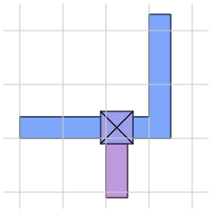 |
When placing hand-routing, you can get better routing results by following the advice illustrated in Figure 3. First, display the routing grid. For example, if the router is using a 8-unit grid (which is true for the standard SCMOS technology), type grid 8. Then place all your hand routing with its left and bottom edges along the grid lines. Because of the way the routing tools work, this approach results in the least possible amount of lost routing space.
In addition to the netlist menu buttons and commands described in Section 4, there are a number of other netlist commands you can invoke by typing in the netlist window. Many of these commands are textual equivalents of the menu buttons. However, they allow you to deal with terminals by typing the hierarchical name of the terminal rather than by pointing to it. If you don't know where a terminal is, or if you have deleted a label from your design so that there's nothing to point to, you'll have to use the textual commands. Commands that don't just duplicate menu buttons are described below; see the magic(1) manual page for details on the others.
The netlist command
extract
will generate a net from existing wiring. It looks under the box for paint, then traces out all the material in the edit cell that is connected electrically to that paint. Wherever the material touches subcells it looks for terminals in the subcells, and all the terminals it finds are placed into a new net. Warning: there is also an extract command for layout windows, and it is totally different from the extract command in netlist windows. Make sure you've got the cursor over the netlist window when you invoke this command!
The netlist editor provides two commands for ripping up existing routing (or other material). They are
ripup
ripup netlist
The first command starts by finding any paint in the edit cell that lies underneath the box. It then works outward from that paint to find all paint in the edit cell that is electrically connected to the starting paint. All of this paint is erased. (ripup isn't really necessary, since the same effect can be achieved by selecting all the paint in the net and deleting the selection; it's a hangover from olden days when there was no selection). The second form of the command, ripup netlist, is similar to the first except that it starts from each of the terminals in the current netlist instead of the box. Any paint in the edit cell that is electrically connected to a terminal is erased. The ripup netlist command may be useful to ripup existing routing before rerouting.
The command
trace [name]
provides an additional facility for examining router feedback. It highlights all paint connected to each terminal in the net containing name, much as the Show menu button does for paint connected to anything under the box. The net to be highlighted may be specified by naming one of its terminals, for example, trace shifter/bit[0]/phi1. Use the trace command in conjunction with the nets specified in router feedback to see the partially completed wiring for a net. Where no net is specified, the trace command highlights the currently selected net.
Last updated: January 9, 2024 at 4:41pm