
The XCircuit Tutorial Part 1: Drawing with XCircuit
Table of Contents
- Notes Notes
- Task 1 Change an option from the menu
- Task 2 Draw a line
- Task 3 Move an object
- Task 4 Change the properties of a polygon
- Task 5 Change the page
- Task 6 Select an object from the user library
- Task 7 Use a keyboard macro to create an arc
- Task 8 Zooming and panning
- Task 9 Selection of multiple elements
- Task 10 Saving a file
- Task 11 Loading a file
- Task 12 Recovering from a crash
- Task 13 Entering Text
- Task 14 Making curves and paths
- Task 15 Dealing with over/under arrangement of elements
- Task 16 Making user-defined objects
- Task 17 Editing objects and elements
- Task 18 Generating complex geometric shapes
- Task 19 Investigating other xcircuit commands
- This tutorial assumes the use of a 3-button mouse. Users of 2-button
mice can do one of three things:
- If the X server supports 3-button emulation, the middle mouse
button can be selected by simulataneously pressing the left and
right mouse buttons.
- XCircuit defines the key sequence Shift-Button1 as an
alternative to the middle mouse button.
- XCircuit started with the option "-2" remaps the button
and key bindings. In this case, all bindings for "mouse button 2"
or the "middle mouse button" will be remapped to the right mouse
button, and all bindings for the right mouse button will be
remapped to the backspace key.
Acquaint yourself with the arrangement of menu buttons and pulldown menus.
- Press the button labeled "Options" with mouse button 1 and
hold down the button while you drag the cursor aroundwith the mouse
(the Tcl/Tk version does not require the button to be held down).
- Keeping the mouse button pressed down, move down to the "Elements" button.
Each button will highlight as you pass through it.
- Put the cursor on top of the arrow icon at the right side of the "Elements"
button. You should see a secondary menu titled "Elements" pop up. The
title is the topmost entry of the menu. It has no function and does not
highlight when the cursor is overtop it.
- Keep moving down to the "Color" button and again move the cursor over
the arrow icon. The third and final menu of colors will pop up. Note
that one item, "Inherit Color" has a check mark on it (a filled
checkbox in the Tcl/Tk version). The check mark denotes that this
entry is the current default color.
- Move down to the purple color button and release the mouse button there.
The menus will disappear. You have just changed the default drawing
color to purple. The color button on the toolbar should be purple
now, reflecting the change in default drawing color.
- Repeat the procedure up to step 4. When you enter the "color" menu you
will see that the purple color button is now checked, showing that
purple is the default drawing color.
- The toolbar duplicates many of the actions available from the pull-down
menus. Press the color button on the toolbar. You will see the same
menu that you saw in step 4 above, only now it is a pop-up, rather
than a pull-down, menu. The toolbar button is a convenient way to
get to the same menu, faster.
Throughout the tutorial I will refer to the menu items using the pulldown
hierarchy, with an arrow ("->") wherever you need to go to a submenu. So
the "Inherit Color" menu item would be referred to as
"Options->Elements->Color->Inherit Color".
Now that you understand the function of the menu buttons, it's time to learn
how to draw something. The simplest and most common thing to draw in xcircuit
is a series of connected line segments (unclosed polygon), otherwise know
for purposes of schematic drawings as a "wire".
- Make sure that the toolbar "Wire Button"
 is highlighted.
This toolbar button binds the left mouse button tap to the wire
drawing function.
- Tap mouse button 1 anywhere in the drawing area and release it
immediately. If you wait too long to release the button, xcircuit will
interpret it as trying to "grab" an element on the screen, and nothing
will happen (because there aren't any elements yet to grab). If this
is a persistant problem for you (which can happen, for example, if you
are working over a network connection or your processor is heavily
loaded), you can disable the function from the "Options" menu (see
below).
- Move the cursor around the screen. A purple line (because you chose
purple to be the default color in Task 1) will appear between the
origin point and will track with the cursor.
- Tap mouse button 1 again to finish a line segment. A new line
will begin at the point the first one left off. Do this several times
to form a polygon. Finish the polygon by tapping mouse button 2.
- Repeat steps 2 through 4 but finish by tapping mouse button 3.
The last line you have just created will disappear. You have just
canceled the last line segment. You will continue to be
in wire drawing mode as long as at least one wire segment exists.
Continue tapping mouse button 3. When the last segment
disappears, you are no longer in wire drawing mode.
- Repeat steps 2 through 4 but finish by tapping the escape key.
The entire set of lines you created will disappear. You have just
canceled the whole wire drawing operation.
- Repeat steps 2 through 4 but start by tapping the w key
instead of the left mouse button. The effect is the same. The
w key has the same binding as the left mouse button in
wire mode. But the w key continues to initiate wire drawing
even when XCircuit is in a different drawing mode.
- Click on the toolbar "Pan Button"
 . This takes
XCircuit out of "wire drawing mode" Tapping left mouse button
will now move the location of the drawing in the window rather
than starting a wire. However, the "w" key will continue to
create wires.
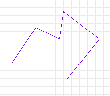
A purple wire (unclosed polygon), drawn with mouse clicks in XCircuit.
For most operations in xcircuit, tapping mouse button 1 will begin or
continue an operation, tapping mouse button 2 will finish it,
tapping mouse button 3 will cancel the operation or most recent
part of it, and the escape key will cancel the entire operation.
The behavior can be slightly different depending on the circumstance, and
the behavior for pressing buttons 1 and 2 is very different, as
demonstrated in Tasks 3 and 4.
Mouse button 1 does have one very different function than that described
in the last task. It can be used to "grab" hold of an element for moving.
- Press mouse button 1 close to a line of the polygon you just
drew. Hold down the button. The line should turn a gold color,
indicating that it has been "selected". If instead nothing happens,
then the cursor is too far away from the line. Releasing the button
releases the object.
- Try grabbing and releasing the polygon from different distances to get
a feel for how close you must be to the object in order to grab it.
- Now grab the polygon, and with the mouse button held down, move the
cursor across the screen. The polygon will follow the cursor. This
is how you move an object in xcircuit.
- As mentioned above, not everyone likes this method of pressing and
holding down the mouse button to drag, and sometimes a slow processor
or network connection can make it difficult to use. In such cases,
go to the "Options" menu, and un-check the box by the item "Allow
HOLD mode". Once the HOLD mode has been disabled, it will no longer
be possible to drag elements around the drawing window as described
in Task 3. Instead, click the "Move Button"
 in the toolbar. This
binds the mouse button 1 tap
function to the move action. In this mode, you can move an element
either by pressing and dragging, as described above, or by tapping
and releasing the button, moving the selected element around, then
tapping and releasing again to place the element.
mouse button 2 also has a selection function; in fact, it has two of
them. In a normal drawing mode, it can be used to select objects for editing
or changing properties. In this task you will use mouse button 2 to
select the polygon you just created in order to make it a dashed line.
- Select the object by tapping mouse button 2 with the cursor near
to the object. The object will turn gold, indicating that it has been
selected.
- Tap mouse button 3, and the selection will be canceled.
- Investigate the other form of selection by pressing mouse button 2
starting below and to the left of the polygon, and dragging the cursor
to the top and right of the polygon. A green box will follow the
movement of the cursor.
- When the box completely surrounds at least one of the endpoints
of any line segment of the polygon, release the button. The polygon
should be selected.
- Click mouse button 3 to deselect the object.
- Repeat steps 3 through 5, noting that if no endpoint of the polygon
is contained within the select box, then the polygon will not
be selected.
- Select the polygon but do not deselect it.
- Go to the "Options->Elements->Border" submenu and select option
"Dashed". Alternately, the same menu can be accessed from the
toolbar "Line Style" button
 .
When you release the button, the polygon will be drawn
in dashed lines. To unselect the polygon, click the right
mouse button, or hit the "escape" key.
- Experiment with the different Colors, Fill-styles, and Border-styles
available in the menus and toolbar
"Line Style"
 ,
"Fill"
  , and
"Color"
  buttons. Some of the many varieties are shown below.
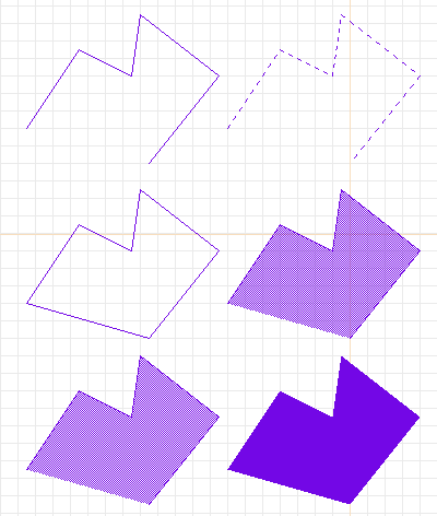
More purple polygons.
Top left: original. Top right: dashed.
Center left: closed. Center right: stippled (50% stipple).
Bottom left: opaque stippled. Bottom right: filled solid.
Xcircuit has multiple pages. There are three ways to change the current
drawing page, from a key binding convenience function, from the menu, or
from the toolbar.
- Select the menu item "Window->Goto Page->Page 2". The polygon
you just drew on Page 1 will disappear, and you will be on a
clean page, with the bottom left-hand window saying that you
are editing "Page 2".
- Go back to Page 1 using the key binding: With the cursor
in the drawing area, press the "1" key. You will be back on
page one.
-
 Key "Page Down" will increment the page number. Try this to
move up from page one to page ten (TCL version only).
-
 Key "Page Up" will decrement the page number. Try this to
move down from page ten to page one (TCL version only).
- Keys "1" through "9" and "0" will get you instantly to pages
1 through 10, respectively. There are no keys for changing
to pages higher than 10; to do so, either use the menu, the
page directory (see below), or the "Page Up" and "Page Down"
keys.
- Click on the toolbar "Page Directory" button
 . This will
give you a view of all the pages currently in XCircuit. Page
1 is initialized on startup and so is always present in the
page directory. Pages 2 through 10 have placeholders in the
page directory, even if the pages have not yet been created
for drawing. If more than ten pages are created, they will
all be displayed in the page directory. From the directory
page, click on the top of any page to go directly to that
page.
- End this task on Page 2, which is currently empty.
Another common task in xcircuit is to grab an object from the object
library and place it on the drawing.
- Select the "Window->Show Library" button from the menu, or press the
"l" (that's "ell" as in "library") key in the drawing window, or
select the "Library" button
 in the toolbar.
I cannot over-stress that keyboard bindings, once memorized, are
more convenient to use than their menu button counterparts. Almost
always, the letter or symbol used for the macro is meaningful and
easy to remember (like "a" for "arc", "s" for "spline", "p" for
"pan", "c" for "copy", etc.).
- A page will appear, showing a number of circuit objects in the
built-in object library.
- Grab one object by moving the cursor over top it and pressing and
holding mouse button 1 (you may also just tap and release;
this is similar to the "move" operations described in Task 3).
As soon as the button is pressed, the object library will
disappear, and you will be dragging the
object around Page 2, from which you called up the library. When
you release the button, the object will be placed and deselected.
- Select the object by tapping on it with mouse button 2.
Try changing the border style to dashed. You will see that
nothing happens. This is because object instances from the
library are made up of basic elements like polygons,
arcs, and splines, but they are composite objects which
do not have properties like "Fill-style" and "Border-style".
However, object instances do have the property of color, and
also the property "size" which simple elements like the polygon
do not have (aside comment: The color property only works for
elements of the object instance that are marked with "inherit
color". Elements in an object with specifically set colors
remain that color regardless of what color is chosen for the
object instance as a whole).
- Select the object again (if you have not already done so), and
then select the menu item "Options->Elements->Object Size" (an
easier way to get there is the "Rescale Mode" button
 in the toolbar).
- A window will pop up asking you for an object size. Place the
cursor somewhere inside the popup window and change the default
size of "1.00" to "1.5".
- Press the "Okay" button. The popup window will disappear and
the object will now be 1.5 times its original size (that is
to say, its length and width will each be 1.5 times their
previous value. In the interest of not distorting schematic
drawings, it is not allowed to separately rescale width and
height).
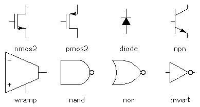
Part of the default circuits built-in library.
Every basic element in XCircuit (wires, arcs, curves, labels, paths, and
object instances) can be created in the same way by any of four
basic methods: 1) menu item selection, 2) toolbar mode selection,
3) key binding, and 4) command-line entry. The menu selections simply
invoke the toolbar button, so these will be treated as the same method.
Command-line entry is not treated in this tutorial.
As mentioned above, keyboard macros are the quickest method. In this
task, you will create an arc by both the toolbar and key binding
to show the difference.
- Select the menu item "Edit->Make Arc", or, equivalently, the
toolbar "Arc" button
 The button will be highlighted to indicate that arc drawing mode
is in effect.
- Place the cursor where you want the arc center to be and tap and
release the left mouse button. Drag the cursor around the screen.
An arc will follow the cursor, its center at the original position
and the diameter determined by the current mouse position.
- Tap and release mouse button 2 to finish.
- Begin a new arc (repeat step 2).
- This time, instead of ending with the middle mouse button, tap
and release the left mouse button again. The arc diameter will
now be fixed, and you will be editing the angle of the
first endpoint. If you keep pressing mouse button 1, you
will be able to edit, in turn, both endpoint positions and the
ellipse axis. Whenever the circle/arc/ellipse is the way you want
it, tap mouse button 2 to finish. At any point in this
operation, if you tap mouse button 3, you will cancel the
last edit (all changes since the last tap of the left mouse
button). Tapping key "escape" will cancel everything and
remove the arc, the same behavior as tapping mouse button 3
multiple times until all edit operations have been canceled.
- Now, create an arc by tapping the "a" key while the cursor is in the
drawing area. This works exactly like the method described above,
except that it can be used in any mode, not just arc drawing mode.
- Note that ellipses in XCircuit can be rotated to arbitrary angles.
However, this cannot be done by editing the ellipse itself. If
the ellipse is placed in an object (see Task 15, below), and the
object instance is rotated, then the ellipse will be rotated with
it. To rotate a single ellipse, make an object out of (just) the
ellipse, then rotate the object instance.
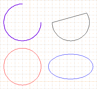
Some differenct arcs.
Top left: linewidth of 1.5, first endpoint at 90 degrees.
Top right: closed arc.
Bottom left: red circle. Bottom right: blue ellipse.
- Pan the screen to be centered on the arc by placing the cursor close to
the center of the arc and tapping the "p" key.
- Pan the screen by selecting menu item "Window->Pan" or clicking the
toolbar "Pan" button
 .
This will put XCircuit in "pan mode", with a picture of a hand as
the cursor. Tap mouse button 1 to begin repositioning the
screen, and tap it again to fix the position.
- Pan the screen by half-window amounts using the keyboard arrow keys.
-
 Pan the screen up
or down using the mouse scroll wheel.
- Tap the "Z" and "z" keys to zoom in and out, or select the menu items
"Window->Zoom In" and "Window->Zoom Out", or equivalently, the toolbar
"Zoom In"
 and
"Zoom Out"
  buttons.
Note how the scrollbars on the side and bottom of the screen change
with the scale of the drawing.
- Pan the screen by tapping any mouse button on either of the scrollbars,
or pressing and dragging the scrollbar.
- Zoom to a selected area of the screen by making a green selection box
like you did in Task 4, step 3. However, instead of releasing the
button in order to make the selection, type the "Z" key (shift-z)
while the mouse button is still pressed down. The screen area will
zoom to the area of the green box. If you instead press the "z"
key (no shift), the screen area will zoom out such that the previous
window boundaries fit in the area of the box.
- Click on the black square at the point where the scrollbars meet to
center and expand the view of the current drawing to fit and fill
the window. This is equivalent to the menu item "Window->Full View".
Note: The selection mechanism for multiple elements changed
in XCircuit version 3.3.7. For a description of the mechanism used
prior to this version, click here.
- Clear the current page by choosing the menu item "File->Clear Page".
There is no keyboard macro for this command, to prevent accidental
erasure of the screen (which cannot be undone with the "Undo"
command).
- Grab several objects from the library (see Task 6) and place them
on top of each other in the middle of the page.
- Decide on one object which you will move, leaving the others where
they are.
- Now press mouse button 1 as if you were going to select the
object you want to move. Because the command is ambiguous---the
program doesn't know which one or ones of the objects you really
want to select---the program will arbitrarily choose one of them.
- If the object highlighted (gold) is the one that you want to select,
you're done. If not, then release the mouse button, and press it
again. XCircuit will select a different element this time. Repeat
until you have the object instance you want to move.
There are various ways to pick and choose a collection of elements at
one time. Each of the selection mechanisms in XCircuit behaves
differently in this respect. The different mechanisms are outlined
below. Some combination of them can always get the selection you want.
- Selection and move with mouse button 1 press-and-drag
- This method selects exactly one element, but if
more than one element meets the selection criteria,
a different element will be picked on each successive
button press. The criteria for picking elements is
for the pointer to be "near" a line, arc, curve, or
path, or inside the bounding box of a label or
object instance. Object instances are recursively
searched for pointer being "near" an element internal
to the instance. The definition of "near" has a
wider sense for the recursive search, so that, for
example, the center of a NAND gate satisfies the
search. This method is only used for grabbing and
moving elements. If elements are selected prior to
using this selection method, no new selections will
be made, and these elements will be moved. All elements
are unselected when the button is released.
- Single selection with mouse button 2 click
- This method adds another selection to the existing set.
The criteria for picking elements are the same as for
the button-1 selection. Elements remain selected
after the button release, until one of the methods
for selection removal (see below) is invoked.
- Area selection with mouse button 2 press-and-drag
- This method selects all elements that match the
selection criteria. The criteria are slightly different
from those for the single-button selections. Labels
and object instances are selected if the area rectangle
covers one or more corners of the label or instance
bounding box. Polygons and curves are selected if an
endpoint or breakpoint is within the area box. Arcs
are selected if the center point is within the area
box (which is usually a poor criterion for very large
circles).
- Undo selection with mouse button 3 click
- Mouse button 3 unselects all elements.
- Undo selection with "undo"
- The "undo" function (key macro "u") undoes the
last selection event. It will remove a single item
from a set incrementally selected using mouse button 2,
or restore one or more items unselected using the "x"
key macro (see below).
- Remove selection with "x"
- The "x" key macro removes individual elements from
the current selection set. The criteria for picking
elements are the same as for the button-1 and button-2
selection methods. Only one element is deselected, in
the same manner as the selection. If more than one
element is near the pointer, and the element picked by
the unselection mechanism is restored using undo,
the subsequent use of "x" will unselect a
different item.
Since the main purpose of xcircuit is to create publishable-quality picutures,
it is necessary to understand a little bit about the PostScript output which
it writes. First I will show you how to save and load a file.
- Choose a page which you have been drawing on, or create a drawing to
save.
- Select the menu item "File->Format Page Output". You will get a popup
window that looks like the figure below.
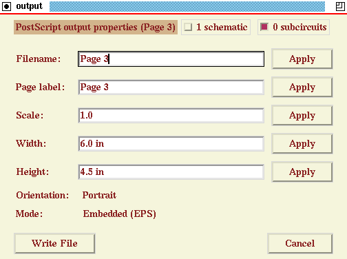
The file properties popup window.
- If you tap the button labeled "Write File". You will get a message in the
bottom message window saying "Warning: Enter a new name". Nothing
has been written at this point (NOTE: Some versions of XCircuit
do not have a default entry in the Filename: field, and will save
a file called ".ps", so be aware of this. The behavior has been
corrected but exists in some versions).
- Change the filename. Move the cursor over the window containing the
filename. Delete the current file name and type in a new one.
When you are done, either hit the RETURN key or tap the
button labeled "Okay" (both actions have the same effect).
- Important note: If the name has no extension, an
extension ".ps" will automatically be added when the file
is written. If an extension, for instance ".eps", is written
in the filename, then it will be used. XCircuit does not
differentiate between encapsulated and non-encapsulated files by
the file extension, but rather by the contents of the file.
- When you change the filename, the page label will be changed to
match the filename, and the bottom left-hand message window will
now say "Editing: " followed by the page label name, followed by
the page number in parentheses.
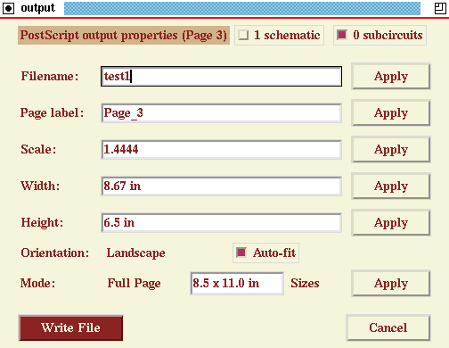
Changes to the filename, orientation, output type, and to the
scale using the "auto-fit" function.
- If the filename you chose already exists on the disk, the button
which previously was labeled "Write File" will now say "Overwrite
File", the computer will beep, and the bottom message window will
say "Warning: File exists".
- Tap the button labeled "Cancel". The window disappears; because
you did not tap the "Write File" button, nothing was written,
although the filename change has been registered.
- Select "File->Format Page Output" again to bring the window back.
This time, tap the "Write File" button. The file will be written
to the disk current directory, and the button which previously
said "Close" will now say "Done".
- The file which has just been saved is already in a PostScript format.
You may view it with any PostScript previewer (ghostview is recommended).
Look at the file in the previewer. Note that the drawing has been
centered on the page. The size of the drawing should be exactly the
width and length reported in the window prior to saving.
- Now, click on the button labeled "Embedded (EPS)". You will get two
choices, "Embedded" or "Full Page". Choose "Full Page". Now, you
will see an additional window showing the page size (default letter
when units are in inches, or A4 when units are in centimeters).
There is a button labeled "Auto-fit" (unselected).
 In the TCL version,
there is another button labeled "Sizes". Select a Tabloid size
either by selecting "Tabloid" from the "Sizes" menu (TCL version only),
or by editing the page size window and replacing "8.5 x 11.0" with
"11.0 x 17.0", and hitting return to accept. Note the scale,
width, and height entries. Now, select the "Auto-fit" button.
The scale of the drawing changes such that the drawing fits in the
selected page size, with minimum 1-inch margins.
- Note: Margins can be changed by selecting a scale which fits
the drawing to the selected page size with the proper margins.
For example, "Auto-fit" on a letter-size paper will rescale the
drawing such that the width is 6.5 inches (assuming that the width
is the limiting dimension), leaving 1 inch on either side. However,
you can reduce the margins to one-half inch by changing the "Width"
entry from "6.5" to "7.5". Height will scale accordingly. XCircuit
always maintains aspect ratio, and will never scale the axes by
different amounts.
- Another note: Generally, the page object will be exactly
centered on the output. If this is not the desired behavior,
a bounding box may be explicitly drawn on the page. To do this,
draw a box anywhere on the page. Then, select the box, and
choose menu selection "Options->Elements->Border->Bounding Box".
When this is selected, the rectangle turns light green, indicating
that it is a bounding box. This rectangle will not appear in the
output (however, it is saved and will be reloaded with the rest of
the drawing). With the bounding box present, all output will be
centered on the box, not on the drawing as a whole. Note that by
itself, the box does not "bound" anything. However, if the bounding
box rectangle is present and "Auto-fit" is selected in the output
properties window, then the drawing will be scaled such that the
bounding box fits the output page with 1-inch margins. This allows
a convenient way to either place a drawing in a specific position
on the output page, or to create an output which "zooms in" on a
portion of a large, detailed drawing.
Write All
There is a menu button "File->Write All..." which is meant to be
a quick link for saving a file that is already properly
formatted. It is not a substitute for the "Format Page Output"
dialog, and cannot be used to set the filename. However, from
the "Write All..." dialog, the "Format Page Output" dialog can
be reached by clicking on the button in the column "Pages". If
no changes have been made to the file, then there is nothing to
to in the "Write All..." dialog. However, there is a button
"Force" to force a write anyway; clicking "Force" brings up
the normal "Write All..." dialog with entries for each page.
- Go to a new, unused page.
- Select menu item "File->Read Xcircuit File". You will get a screen that
looks something like the following:
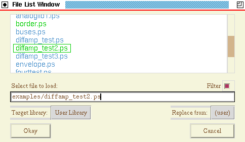
The load-file popup window.
Make sure that you use the function "Read", not "Import". The
import function loads an xcircuit file, merging with any existing
schematic. Importing onto a blank page is essentially the same
as loading, but may end up displaying a different page than that
intended for the tutorial.
- If the file list is larger than the window, you may scroll up and down
the list by clicking mouse button 1 or 2 on the
scrollbar at the right side of the window and dragging it up
and down, or by using the mouse scroll wheel.
- A green box will be drawn around each filename as your cursor passes
over it.
- Find the file that you just saved in the last task. When the green
box is over this filename, tap mouse button 1. The filename
will turn green, and at the same time will be copied into the
text edit box.
- Tap the "Okay" button to load the file.
- If you do not wish to use the scrolling menu, you may type the filename,
with or without the ".ps" extension, in the text edit box,
followed by the RETURN key or tapping the "Okay" button.
- Selecting a directory name in the file list box, including "../" for
the directory one level up, will go to that directory. Entering a
directory name in the text edit box followed by the RETURN
key will also go to that directory.
- If you know where the xcircuit source is kept, then select the
"File->Read Xcircuit File", go to the source directory, go to the
"examples" directory, and load one of the example files, such as
"vcoblock.ps".
- Note: The "Filter" button filters a directory by file extension.
For file loads, this shows only files with the extension ".ps". If
valid XCircuit files have other extensions, such as ".eps", the
filter needs to be disabled to view them.
- The "Target Library" button selects the library page onto
which any new objects found in the file will be placed. By default,
new objects go in the "User Library". Pushing the button will
generate a pull-down menu from which a different library page can
be chosen as the target page for new objects.
- The "Replace from" button selects which, if any, technology
will replace conflicting objects (objects with the same technology
name and same object name) in the file with the version already
in the library. Normally, "Replace from" is either "none", for
which no replacement occurs (conflicting objects are renamed
to avoid problems), or "all", in which case all conflicting
objects are replaced by the existing library version. Typically,
this feature is only needed when a schematic hierarchy is split
into multiple files and an associated project library, and each
file should update its local version of objects (symbols) whenever
a change made to another file has been written back to the
project library file.
System crashes, hangs, power outages, tripped-over power cords, and program
segmentation faults all happen, and many programs are loved or hated
according to their ability to recover from such mishaps. In this task we
investigate the all-important problem of recovering your work after a
crash.
- Draw something on a page, anything at all. You need to spend
at least one minute on the drawing or make at least 20
modifications to the drawing before a backup will be made.
- From the terminal or window manager, kill the XCircuit program
with an explicit kill signal ("killall wish" will do for the
Tcl/Tk version of XCircuit under UNIX).
- Do "ls /tmp" from the UNIX command line. Among the
entries, you should see something like "XC4NoVXK",
a file name beginning with "XC" and followed by six random
characters. Your work is in there!
- To access this crash recovery file, simply type "xcircuit"
at the UNIX command line, without any filename. Specifically,
don't enter, e.g., "xcircuit /tmp/XC4NoVXK",
because then all pages will have the temporary crash recovery
filename rather than the original filename(s).
- XCircuit should then start up with a prompt such as (in the
example above) "Recover file 'Page 1 (Tue Oct 4 14:07:24 2005)'?".
Select "Okay".
- You should get back your lost file, or at least the better
portion of it. XCircuit by default saves once per minute, or
after every 20 modifications to a drawing.
- Note that once the backup is read in, the temporary file is
removed. It is possible to completely lose a file by
responding "Okay" to the "Recover file" prompt, and then
quitting without saving. Unlike most programs, XCircuit
assumes that end-users are not stupid, but on the other
hand, quitting without saving means exactly that.
Xcircuit has a very complicated interface for entering text, which allows
you to change fonts and font styles within a string, make overlines and
underlines, and subscripts and superscripts.
- Go to a new, unused page.
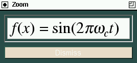
- Let's say you want to type in a fairly complicated expression, like
"f(x) = sin(2*pi*omega_c*t)" (except with Greek letters, of course).
- If you've read your TeX manual thoroughly, and understand all the finer
points of mathematical equation typesetting (if you haven't, you should),
then you know that all the variables should be in italic type.
- Select menu item "Text->Style->Italic". The default text font is now
italic style.
- Select menu item "Text->Font->Times Roman" if it is not checked already.
The default text font is now Times Italic (Times font + Italic style).
- Select menu item "Text->Make Label" or (equivalently) click on the
"Text" button
 in the toolbar. Both actions bind the mouse left
button tap to the creation of text labels. Tap the left mouse button
while the cursor is anywhere on the drawing.
- Alternately, you can just tap the "t" key in the drawing area.
- The green line marks the pointer position, and the "x" marks the
origin (justification) of the text.
- Select menu item "Text->Justification->Middle Justified". You will
see the green "x" move to the center of the line, showing that the
text is vertically centered on its point of origin.
- Alternately, you could type keypad key "6" (on some systems,
Shift-keypad 6) to get center-left justified text.
- Type "f". In the bottom message window, the letter "f" and a vertical
bar "|" appear, showing what's in the string relative to the text
cursor.
- Select menu item "Text->Insert->1/4 Space". This is the proper thing to
do for "italic correction", an extra bit of space necessary after an
italic character followed by an upright character, particularly tall
ones such as "f" and "t" which lean leans rather far to the right of
their character bounding boxes. Alternately, type key combination
"Alt-q" to get the quarter space.
- Select menu item "Text->Style->Normal" (key "Alt-n").
- Type "("
- Select menu item "Text->Style->Italic" (key "Alt-i").
- Type "x"
- Select menu item "Text->Style->Normal" (key "Alt-n").
- Type ") = sin(2"
- Select menu item "Text->Style->Italic" (key "Alt-i").
- Select menu item "Text->Font->Symbol" (key "Alt-f" until font Symbol
is chosen).
- Type "\". A page with the 256 character encodings for the
Symbol font will appear, replacing the current page, as
shown in the figure below.
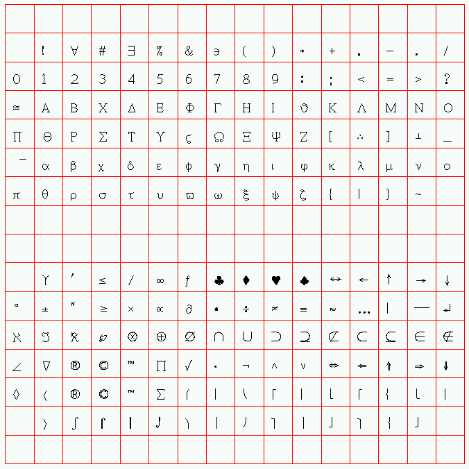
- Click on the "pi" symbol. The screen will immediately
return to the original page, with the "pi" added to the
text line.
- Type "\", then click on the "omega" symbol in the encoding
vector.
- Select menu item "Text->Font->Times-Roman" (key "Alt-f")
- Select menu item "Text->Style->Subscript" (or keypad-minus)
- Type "c"
- Select menu item "Text->Style->Normalscript" (or keypad-enter)
- Type "t"
- Select menu item "Text->Insert->1/4 Space" for another italic
correction (key "Alt-q").
- Select menu item "Text->Style->Normal" (key "Alt-n").
- Type ")"
- Before typing <RETURN> to complete the text, use
the left- and right-arrow keys to move the cursor around inside
the text string. Note how font- and style- changing commands
embedded in the text string can be seen in the message window.
Their position relative to the text cursor is important when
anticipating the effect of deleting (<DELETE> key)
a text command.
- Yes, this is very complicated, but it is also very powerful.

Above: The text figure created in the task.
Below: The PostScript output of the same text from xcircuit.
Typographical Note: ISO-Latin1 encodings define the Greek character "mu"
(µ) to be used for the symbol "micro", which naturally is used often in
circuit schematics. This differs from the Symbol font "mu" in that it matches
the style and properties of the font in which it is defined. Thus, it is
possible to get a Helvetica "mu", a Times-BoldItalic "mu", etc., something
which is virtually impossible to do even in LaTeX(*).
Due to the font size and style matching, this is always preferable to the
Symbol font "mu". To get the ISO-Latin1 "mu" character, (while entering or
editing text) choose Text->Encoding->ISO-Latin1 from the menu, then
either choose Text->Insert->Character or type "\" at the text cursor,
then select the "mu" character from the character array.
Curve drawing is a useful feature of most capable drawing programs. The
concept of paths is a powerful aspect of PostScript which is not
usually found elsewhere. Path definitions are used to create a single
entity out of a string of curves, arc segments, and lines. The resulting
entity has its own color, fill styles, and border styles.
- Go to a new, unused page.
- Click on the toolbar "Curve" button
 to enable
curve drawing mode, and then tap the left mouse button to
start the curve. Alternatively, type "s" in any drawing mode
to start a curve (you can think of "s" as standing for
"spline", although these are Bezier curves, not splines, or you
can just think of the curvy "s" shape. The key "c" is reserved
for copying).
- The first thing you will see is two dotted lines
ending in little "x" marks. These are the curve control points.
- Move the cursor around. Right now you are positioning the
end of the curve but have no control over the control points.
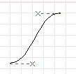
- Place the curve endpoint. If you are satisfied with the shape
of this curve, you can tap mouse button 2 to finish
the curve and quit. However, we'll say that you have more to
do to this curve, so tap mouse button 1 instead.
- You get a message saying "Adjust control point", and the cursor
moves overtop the nearest "x" mark. Now when you move the
cursor, you change the shape of the curve between the fixed
endpoints.
- Move the control point two grid blocks to the left of where it
started (make the control line horizontal with a length of
4 grid blocks).
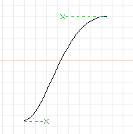
- Click mouse button 2 to finish the curve.
- Simlarly to arc generation, mouse button 1 moves the edit
point between control points, mouse button 3 undoes the
last point edit, and the escape key cancels the curve
creation and deletes the curve, as does clicking the right mouse
button until all edits have been canceled.
- Now we will make a simple path. But it takes more than one element
to form a path. Put the cursor over the curve and tap the "c"
key.
- When you move the cursor, a copy of the curve will follow you.
- While you are dragging the curve copy, flip it by tapping the
"f" key and then the "F" key (one horizontal plus one vertical
flip).
- Place the curve with its endpoints overtop the original curve.
The result should look like the figure below.
- Select both curves by tapping mouse button 2 on top of
each one, or by forming a selection box (see Task 4).
- Tap the "j" key in order to "join" the two curves into a single
path.
- If you now move or select the path, you will find that both
curves act as a single entity.
- Select the path and then select menu item
"Options->Elements->Fill->(black box)". The path will then
become solid black. If you color it blue, it will look something
like the right side of the figure below.
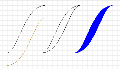
Curves and paths. Left: The curve has been copied and flipped.
Center: The two curves are placed together and joined into a path.
Right: The path is filled and colored as a single entity.
XCircuit from stable version 3.7.27 (April 2011) has another convenient way
to create a curved path, convenient for drawing complicated curve shapes
requiring the curvature to be continuous (no kinks) over the length of the
path. Draw a polygon outline of the curved path you want. Then, select
the polygon and click on menu item "Edit->Make Spline". The polygon will
be converted into a smooth-outline curved path.
XCircuit 3.7 also adds new ways to edit paths to maintain curvature. This
is covered below in Task 17.
Otherwise known as the "stacking order" of the drawing.
- Clear the current page (menu option "File->Clear Page") or go
to a new, unused page.
- Start a box with the "b" key (this is a convenience for
drawing rectangles and squares).
- Click mouse button 2 to finish the box.
- Select the box and choose menu item
"Options->Elements->Fill->(black box)", where the "black box"
is the first menu item in the list. You will now have a black
box. (note that to select the box, the cursor must be near the
edge of the box, not in the middle).
- Select the box again and choose menu item
"Options->Elements->Color->(orange box)". You will now have
a solid, orange box.
- Go to the built-in library ("l" key) and bring back a circuit
object (say, a "nand" gate).
- Place the gate on top of the orange box.
- Make a copy the box ("c" key) and place it beside the first.
mouse button 2 ends the copy command.
- You will notice that the library object suddenly disappeared.
This is because the "copy" command moved the orange box
to the end of the drawing list. Because it is drawn after
the library object, the library object is hidden underneath.
- To get the library object on top again, select everything in the
area of the orange box by forming a selection box around the
orange box (mouse button 2). Tap the "X" key (Shift-X)
to exchange the drawing order of the two elements. The
library object will now be visible on top of the orange box.
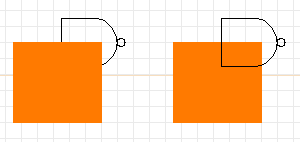
Over- and Under- arrangements (stacking order) of elements.
Note that the "exchange" function has a different use when applied to
only one selected element. A single element will be brought to the
top of the drawing stack, unless it is already at the top, in which case
it will be sent to the bottom. If you have an obscured element that needs
to be shown (such as the "nand" gate in the example above), just select the
element by itself and tap the (Shift-) "X" key, and it will be brought to
the top (made visible).
XCircuit version 3.7 (April 2011) has more features for handling the
stacking order of elements than just the "exchange" function. In
particular, the Tcl/Tk script defines the "[" and "]" keys to move one
or more selected elements up or down one position in the stacking order,
respectively.
One of the most powerful aspects of xcircuit is its ability to deal with
objects on a hierarchical level. Circuits in particular are highly
structured. Often it is desirable to draw a subcircuit and use it
several times. It is much more efficient to draw the subcircuit and
create a user object from it rather than to copy all the
separate elements of the subcircuit every time you want a copy.
This is also true of new circuit components.
Say we wish to create a new circuit component, a dependent current
source.
- Clear the current page or go to a new page.
- We want the dependent current source to look something like the
independent current source (isource) in the built-in library file.
Go to the library and bring back an "isource" object for reference.
- Draw a polygon, as in Task 2. Make it diamond-shaped and three
grid spaces high, two wide (see the figure below).
- Add a line of height one-half-grid space on the top and bottom
of the diamond.
- Now we will do something unusual. We will grab the arrow from
inside the isource object. Edit the original "isource" object
by placing the cursor over it and typing the ">" key (push
object). The page you were on will disappear, and you will
see only the object "isource".
- Using the multiple-selection mechanism described in Task 9,
select the arrowhead and line in the middle of "isource", but
not the surrounding object.
- Make a copy of these two elements with the "c" key.
- While still dragging around the copy of the arrow, return to
the main page by typing the "<" key (pop object). You will
be returned to the original drawing, still dragging the arrow
with you.
- Place the arrow inside the diamond.
- Using a selection box, select all of the components of the
"dependent current source" object you have just constructed.
- Type the "m" key to make the object out of the selected
components.
- You will get a popup box asking for a name for the object.
Type something obvious like "depsource" or "disource".
Spaces are not allowed (if you use them, they will be
converted to underscores).
- Tap the "Okay" button. Now, if you click on the dependent
source, it will be treated just like one of the built-in
objects.
- Type the "L" key to go to the library directory. You
will see that the new object you created is now located
in the User Library. You can click on the User
Library page to go to the User Library, and then click
on the "depsource" object to bring back another instance
of it, just like the built-in objects.
- It is important to be aware of the difference between an
object and an object instance. An object
is a collection of elements that have been collected
together and placed in a library, like the depsource
object created in this task. There is only one such
object. However, many instances of this object may be
created. Each instance may have its own position, scale,
and color but may not otherwise change the contents of
the object, which are shared by all instances (the
method of parameters is the exception to this;
see the discussion of parameters in the schematic capture
tutorial).

Steps in creating a new user-defined object.
You briefly edited the built-in "isource" object in the last task,
but did not change anything. In this task, suppose we want to change
the appearance of the "dependent current source" object we made in
the previous task.
- To edit the object, "push" into it using the ">" key,
as you did for the "isource" in the last task.
- Make the polygon shorter. Put the cursor close to the
top of the diamond and type "e" for "edit".
- Test which element is being edited by moving the cursor
around. If the line, not the polygon, is being edited,
then click the right mouse button or the escape key to
cancel the edit operation, and repeat from step 2.
- Now you will be editing the point position of the polygon.
Move the point down one-half grid space, and tap mouse
button 2 to complete the edit.
- Do the same for the bottom point, moving it up one-half
grid space. Where the two ends of the polygon meet, you
will need to adjust both of the points.
- Extend the lines on the top and bottom to meet the
diamond by editing the endpoints just like you did for
the diamond.
- When you are done, return to the main page by "popping"
out of the object page, using the "<" key.
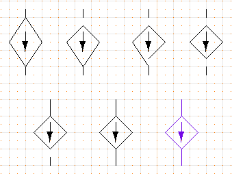
Steps in editing the user-defined object.
XCircuit from version 3.7 makes editing elements, especially polygons,
splines, and paths, much simpler. If you select only a portion of any
of those type elements using an area select box, the points that fall
within the box will be remembered for editing. The whole element
will be shown selected; specific subsets of selected points are
irrelevant if the selection is followed by a function that acts on the
whole element, such as a move or copy function. However, if you follow
the area selection with the "edit" (key "e") function, you can edit all
the selected points as a group. The figures below show how a section of
a path element can be stretched using an area box selection (recall that
the area selection box is generated using the middle mouse button and a
press-and-drag motion).
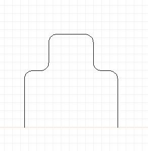
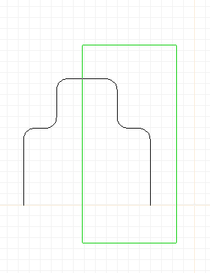
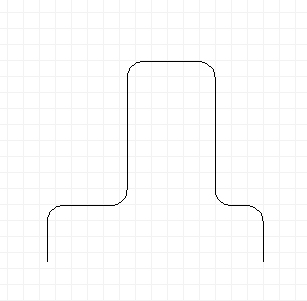
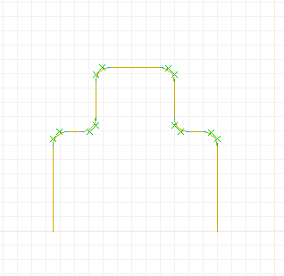
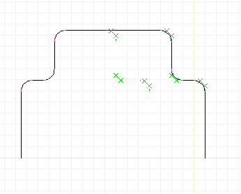
Editing a path object by grouped points (XCircuit 3.7). From top
left, going clockwise:
(1) A path shape made from lines and arcs using the "join" (key "j")
function.
(2) Area select on a portion of the path.
(3) The whole path is shown selected, but the points in the area
box are grouped for editing.
(4) The grouped points are moved to the right.
(5) More grouped editing.
Also in version 3.7, paths containing adjacent spline curves by default
are edited in a way that keeps the curvature smooth across the boundary
between curves. The figure below shows a polygon (left) that has been
converted to a smooth curve (center) by selecting the polygon and using
the "Edit->Make Spline" menu function to generate the curve. On the
right, the curve is being edited point-by-point (key "e"). Control points
of adjacent curves change together, keeping the curve smooth across the
boundary between the two curves. If you need to subvert this behavior to
create a kink at the boundary between two curves, unselect menu item
"Options->Elements->Link Curve Tangents".
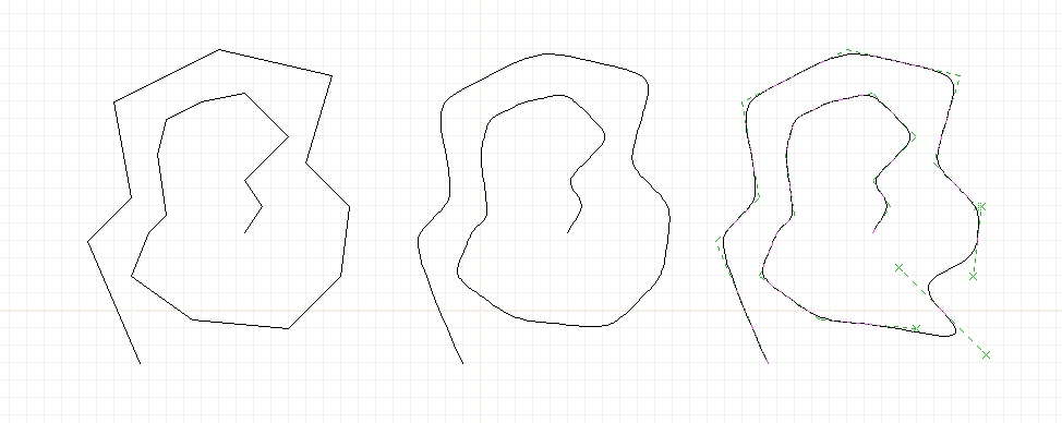
Creating and editing a smooth path.
This can be an incredibly useful feature for general drawing. A
wholesale use of it is necessary to create such extravaganzas as
this rendition of the
JHU Applied
Physics Lab's logo. I have made use of something in PostScript
known as a "path", that is, a linked set of lines, arcs, and splines
which together form the boundary of a single object which can be
bordered, filled, colored, etc. In this task, I will show you how
to generate a picture of a solid cylinder, by making a path consisting
of both ellipses and lines.
- Start with a clean page.
- Create an ellipse as follows:
- Type macro a to start an arc.
- Drag the arc out to some desired size.
- Click the first mouse button three times (to bypass endpoint
editing and go to ellipse axis editing). The position of
the cursor will move from the side of the circle to the top.
- Drag the ellipse minor axis to the desired size and click
the second mouse button to end.
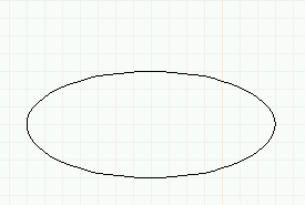
Creating a path object (solid cylinder): top ellipse.
- The whole ellipse becomes the top of the "cylinder". To make the
bottom of the cylinder:
- Copy the first arc and place it well below the first.
- Type macro e to edit (or select edit from the menu
and click on the lower ellipse).
- Immediately type e again or click on the first mouse
button to go to endpoint editing mode.
- Drag the endpoint around to the other side until the
result is the bottom half of an ellipse. Click the
second mouse button to finish.
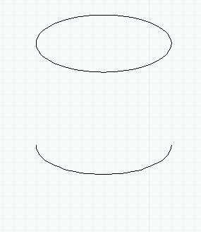
Creating a path object (solid cylinder): bottom (half) ellipse.
- Draw two lines to create the sides of the cylinder.
- Select the bottom and sides of the cylinder, and type the j key
to "join" these segments into a single "path".
- Select everything. If you (individually) select any component of the
path (either the side lines or the bottom ellipse), the whole path
will be highlighted.
- Copy (with the c macro) and place the copy to the side.
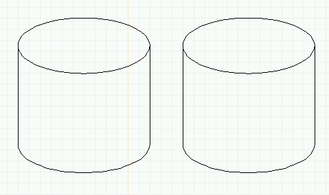
Creating a path object (solid cylinder): Two cylinder frames.
- Select the path (lower part) of the rightmost cylinder.
- Choose menu item "Options->Elements->Fill->(black box)". Now
you can see how to create arbitrary filled shapes.
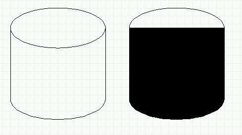
Creating a path object (solid cylinder): Two cylinders, the right one
consisting of a filled path.
- Finish the cylinder in the following manner:
- Color the path shape dark gray.
- Select the ellipse located above the colored cylinder and
perform the same steps to make it filled solid and colored
light gray.
- Use the X keyboard macro to correctly arrange the
elements, with the light gray ellipse on top of the dark
gray path object.
- Place the black wire frame cylinder on the left on top of
the solid cylinder on the right. Hint: Move the
wire frame halfway on top of the solid cylinder, then
arrange the top-to-bottom order of the elements so
that the wire frame ends up on top, then move the
wire frame the rest of the way.
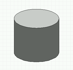
Creating a path object (solid cylinder): Finished cylinder.
Xcircuit version 3.7 has several other ways to make even more complex
geometric shapes. The use of clipmasks and gradients fields is advanced
but can make nice visual effects. A gradient field can be made only from
the command line in the Tcl/Tk version. Use menu item "File->Tcl Console"
(key "%") to bring up the command window, and type the command into it.
The command to create the gradient field in the figure below is:
graphic make gradient {0 0} 5 red gray50
You will need to press the space bar after entering the command to see
the new graphic element, because the command does not automatically refresh
the window view. You can also generate any graphic image using other
graphics programs, export them as GIF or JPG images, and import them into
XCircuit using menu item "File->Import->Import Graphic Image".
To get the series of images in the figure below, do the following steps:
- Create the gradient field graphic as described above.
- Select the graphic element and rotate it 90 degrees ("r" key).
- Draw a cylinder front as a path. This is the same as the series
of steps above, except that a second half-ellipse was added to
the top before creating the path by joining the elements ("j" key).
- Turn the path into a clipmask by selecting menu item
"Options->Elements->Border->Clipmask" (or click the toolbar Border
tool icon, and select the pop-up menu item "Clipmask"). The color
of the path will turn to light blue, showing that it is now a
clipmask (the light blue border will not appear in the final printed
output. If you wish to remove the outline, deselect global option
"Options->Show Clipmask Outlines". However, when clipmask outlines
are not shown, it is very easy to lose track of the (invisible!)
clipmasks!
- The graphics rendering engine must first apply a clipmask and then
render other items through that clipmask, so somewhat counterintuively,
the element that is clipped by the clipmask must be the element
above the clipmask in the drawing stacking order. The clipmask
will always apply to the single element above it in the stacking
order. If you have followed the steps above, then the new clipmask
was the last element created, and so is on the top of the stack, and
on top of the gradient field we want to clip. So select both the
clipmask outline and the gradient field, and type key "X" (exchange),
or else click on just the clipmask outline and type key "]" (lower
stacking order) to put the gradient field above the clipmask. You
should end up with the figure on the right of the drawing.
- If you want to clip multiple elements with the same clipmask, you can
gather all of those elements into a user object, then clip the user
object instance. You should also be aware that clipmasks can be
hierarchically nested, for even more complicated clipping effects.
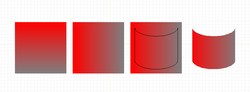
Creating a clip path and gradient field.
By now you should understand the basic user interface of xcircuit and be able
to get around the menus, the drawing area, be able to handle the popup
prompting windows, load and save files, write text, and create polygons,
arcs, curves, paths, and user objects. Of course, we have just touched
the surface of xcircuit capabilities. A list of features can be
found on the XCircuit Reference web page
and will help you find out all the things that can be done with the
program. Also, don't miss the Schematic Capture
Tutorial. If you have the TCL-enabled version of XCircuit, you may
also want to look at the XCircuit TCL Reference
page for a listing of command-line commands.
 Back to the xcircuit home page. . .

| email:
| 
|
Last updated: October 28, 2025 at 9:41am


 is highlighted.
This toolbar button binds the left mouse button tap to the wire
drawing function.
 . This takes
XCircuit out of "wire drawing mode" Tapping left mouse button
will now move the location of the drawing in the window rather
than starting a wire. However, the "w" key will continue to
create wires.

 in the toolbar. This
binds the mouse button 1 tap
function to the move action. In this mode, you can move an element
either by pressing and dragging, as described above, or by tapping
and releasing the button, moving the selected element around, then
tapping and releasing again to place the element.
 .
When you release the button, the polygon will be drawn
in dashed lines. To unselect the polygon, click the right
mouse button, or hit the "escape" key.
 ,
"Fill"
  , and
"Color"
  buttons. Some of the many varieties are shown below.

 . This will
give you a view of all the pages currently in XCircuit. Page
1 is initialized on startup and so is always present in the
page directory. Pages 2 through 10 have placeholders in the
page directory, even if the pages have not yet been created
for drawing. If more than ten pages are created, they will
all be displayed in the page directory. From the directory
page, click on the top of any page to go directly to that
page.
 in the toolbar.
I cannot over-stress that keyboard bindings, once memorized, are
more convenient to use than their menu button counterparts. Almost
always, the letter or symbol used for the macro is meaningful and
easy to remember (like "a" for "arc", "s" for "spline", "p" for
"pan", "c" for "copy", etc.).
 in the toolbar).

 The button will be highlighted to indicate that arc drawing mode
is in effect.

 .
This will put XCircuit in "pan mode", with a picture of a hand as
the cursor. Tap mouse button 1 to begin repositioning the
screen, and tap it again to fix the position.
 and
"Zoom Out"
  buttons.
Note how the scrollbars on the side and bottom of the screen change
with the scale of the drawing.


 in the toolbar. Both actions bind the mouse left
button tap to the creation of text labels. Tap the left mouse button
while the cursor is anywhere on the drawing.


 to enable
curve drawing mode, and then tap the left mouse button to
start the curve. Alternatively, type "s" in any drawing mode
to start a curve (you can think of "s" as standing for
"spline", although these are Bezier curves, not splines, or you
can just think of the curvy "s" shape. The key "c" is reserved
for copying).


 Back to the xcircuit home page. . .

